|
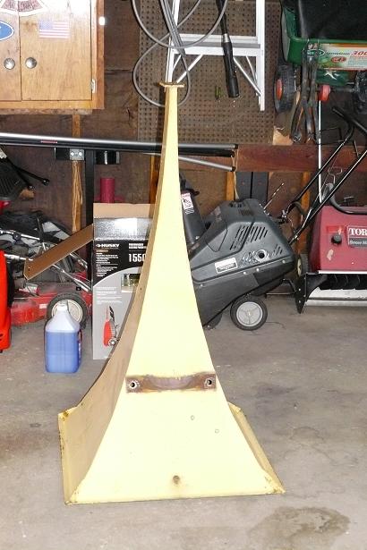
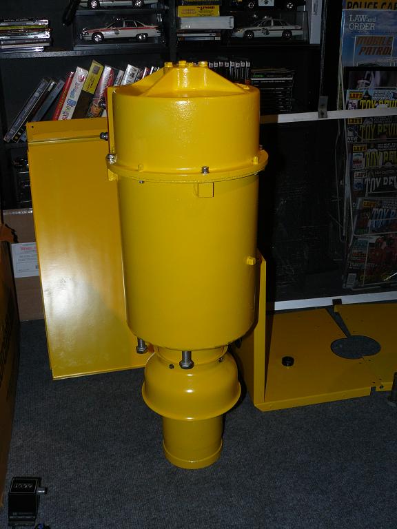
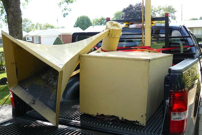
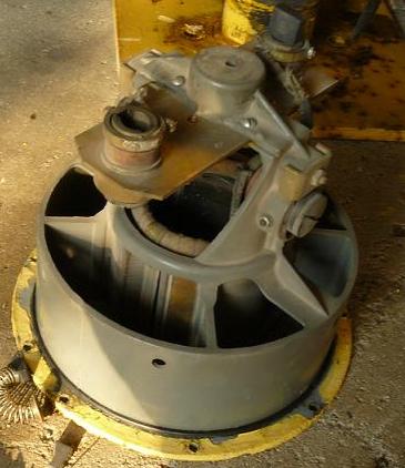
Here's the siren when I got it home.
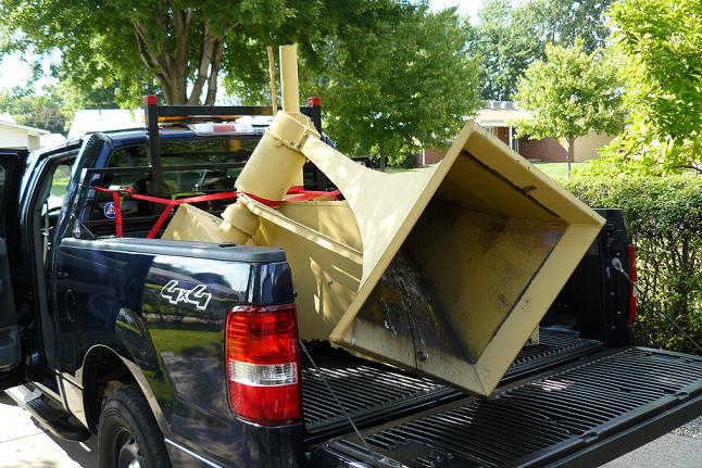
Another View
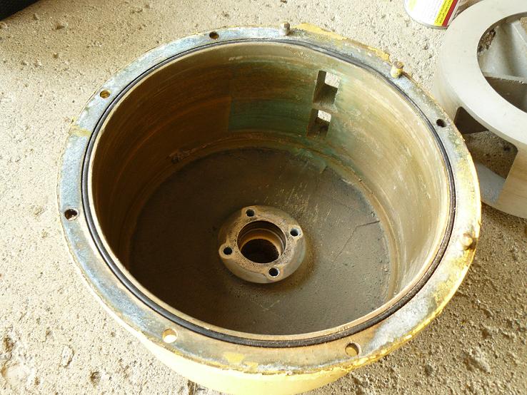
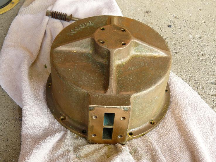
Here's the underside of the Compressor Cover
Another View, You can see the darker color peaking thru the last color the siren was painted.
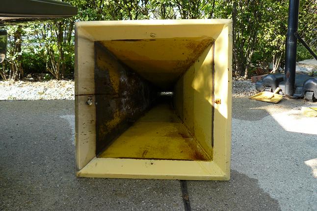
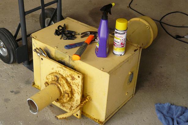
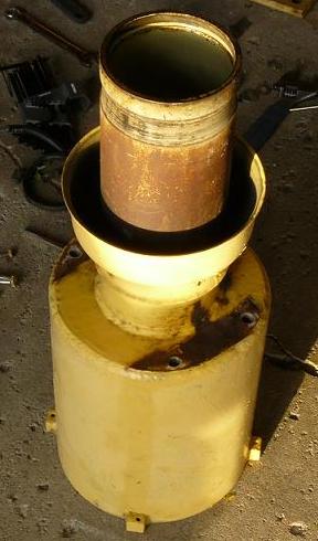
Projector after a good powerwashing
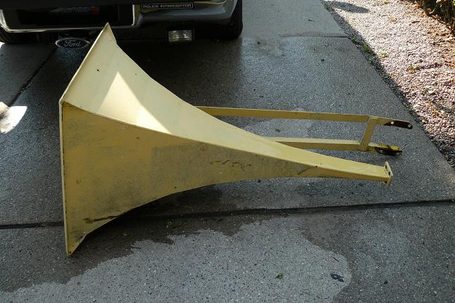
Another View
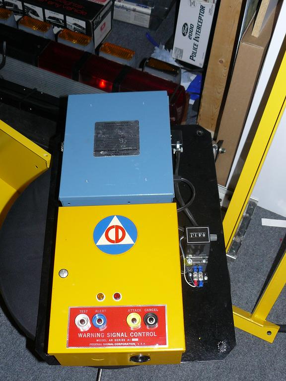
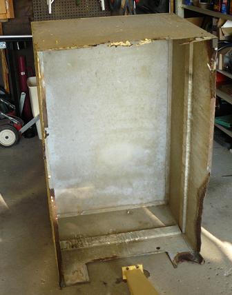
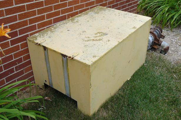
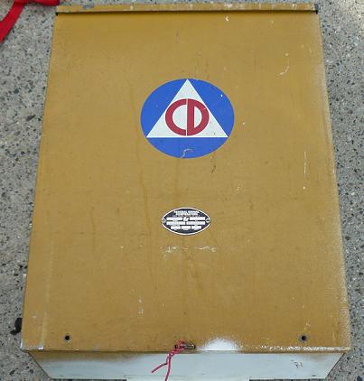
Radio / AR Timer Cabinet
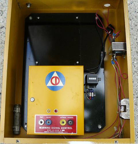
Inside the cabinet. The radio is Missing in this picture.
I have acquired a replacement to be put back in.
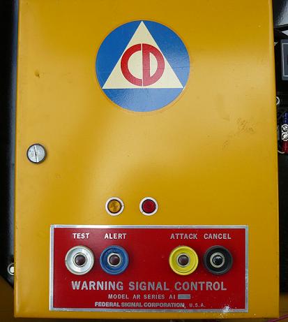
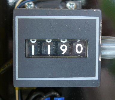
Close up of the AR Timer
Closeup of the Counter. This siren was activated 1190 times since it was installed.
I would estimate that it was put in the late 1950's
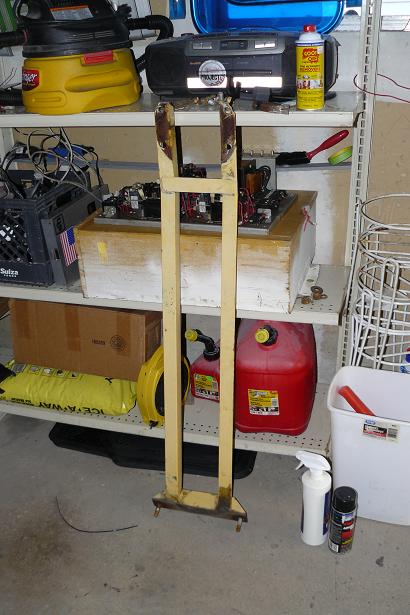
Here's the projector support. You can see where it's started to rust.
Here's the inside of the RCM panel

Here's a bottom view of the mounting flange.
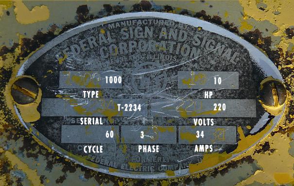
Using some Citistrip, I managed to remove some of the layers of paint to reveal the old circle "F" Thunderbolt logo.
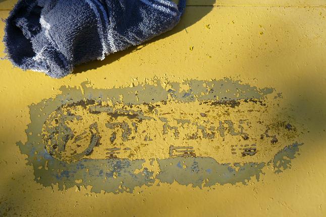
I also used it on the rotator tag.
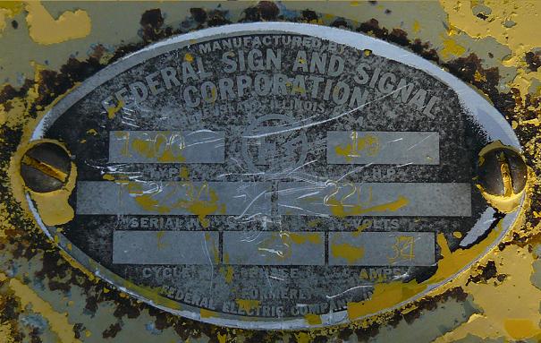
The text is hard to read, so I added it to this picture
Close up of the single tone chopper housing.
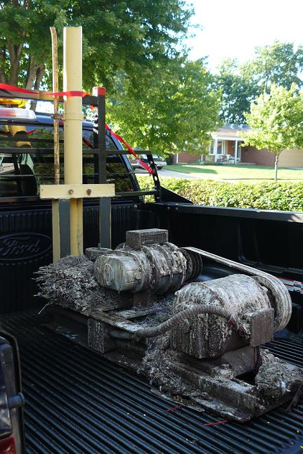
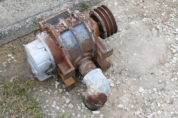
Here's the 3 Phase compressor and motor. This is a 20 Lbs bird nest.
After 2 hours of removing and cleaning. I could not save any of this. I have received a Single phase compressor/motor
to replace this one.
Here's the rusty compressor. It was locked up.
Inside the rotator cabinet
Other side.
The rotator motor is 3 phase. I have replaced this with a single phase.
Chopper cap removed, This part is Brass
Chopper Motor
An upsidedown view of the single tone chopper
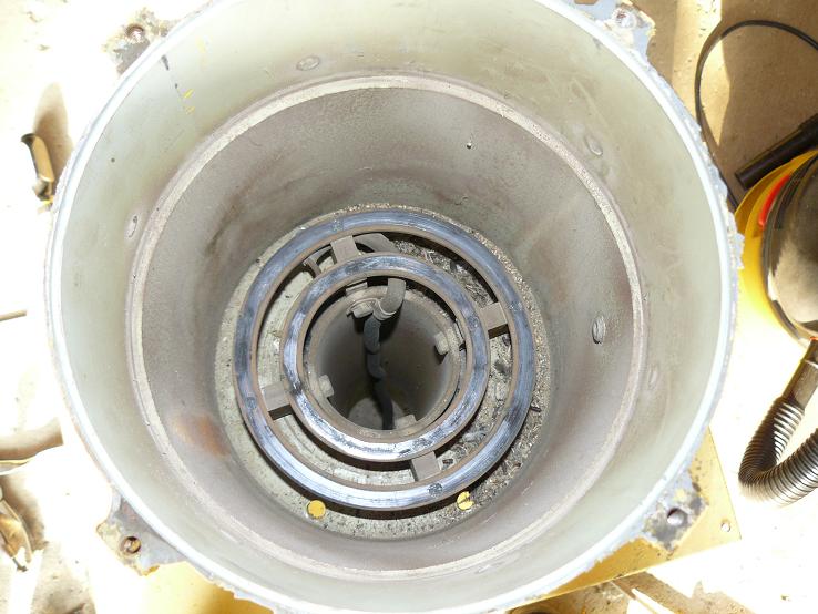
Inside the chopper housing. you can see the contact rings.
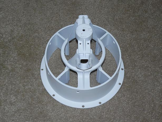
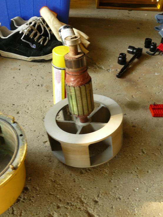
The skeleton of the rotator mount
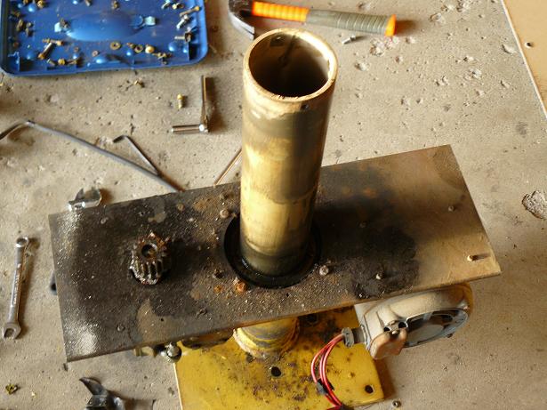
Chopper housing. A bit rusted, but no signs of grease. This is one of the many parts that required annual greasing. So it
hadn't been checked for awhile.
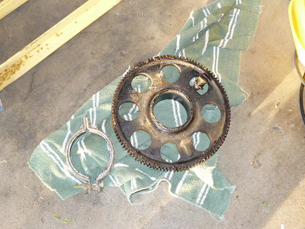
Greasy rotator gear, one of the few parts that still had grease on it.
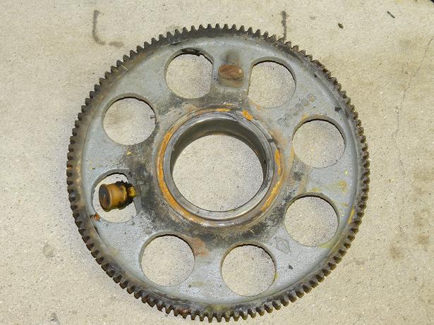
Here's the same part after a degreasing
Closeup of contact rings
After soaking in stripper for a few hours and some elbow grease, here's the chopper cap all clean.
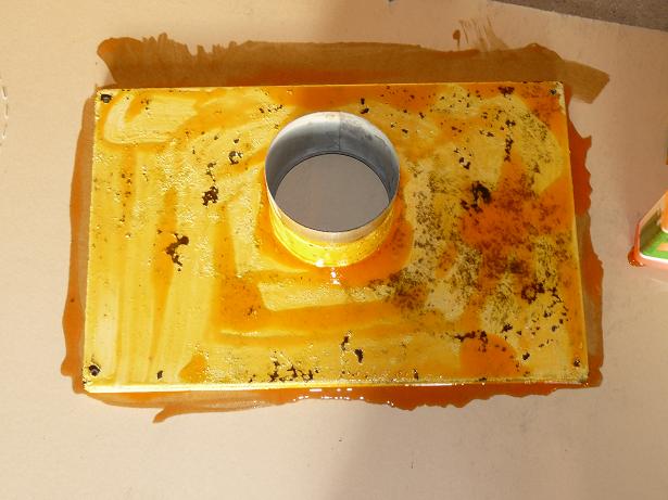
Here's the rotator cabinet top soaking in stripper.
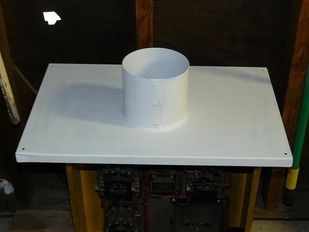
Here's the same part with a fresh coat of primer
Here's a pic of the started removal of paint on the projector. The red spots are from the lead test kit. Red means that lead
is present. After seeing that, I had to go get some more safety protection, so I could remove the rest safely.
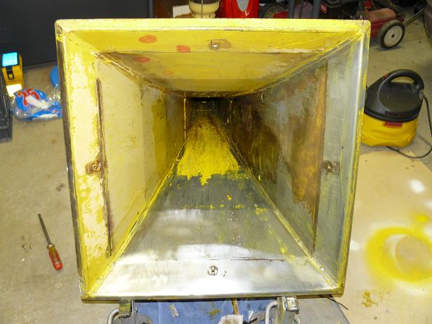
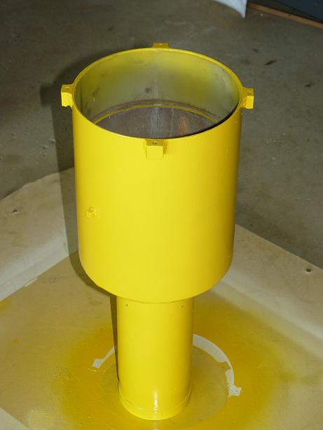
HERE ANOTHER PIC OF THE PROJECTOR CONE
HERE IS THE CHOPPER HOUSING. ALL REPAINTED
THE PAINT COLOR I CHOOSE THAT LOOKS CLOSE TO ORIGINAL CD YELLOW IS "SUNBURST YELLOW"
HERE IS THE CHOPPER MOTOR WINDINGS BRACKET.
RUST REMOVED AND NOW IN PRIMER.
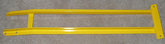
HERE IS THE SUPPORT ARM
ALL RUST REMOVED AND REPAINTED
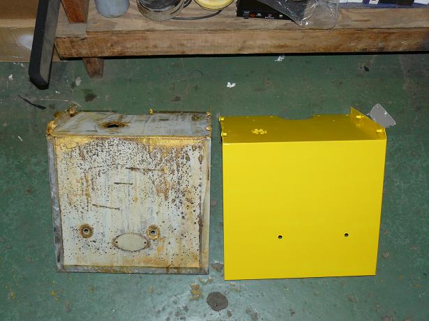
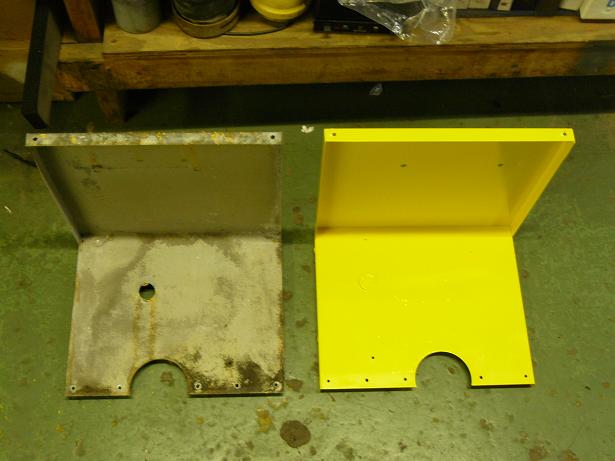
HERE ARE THE ROTATOR CABINET SIDE PANELS.
YOU CAN SEE ONE IS CLEANED UP BUT NOT REPAINTED, AND THE OTHER WAS REPAINTED
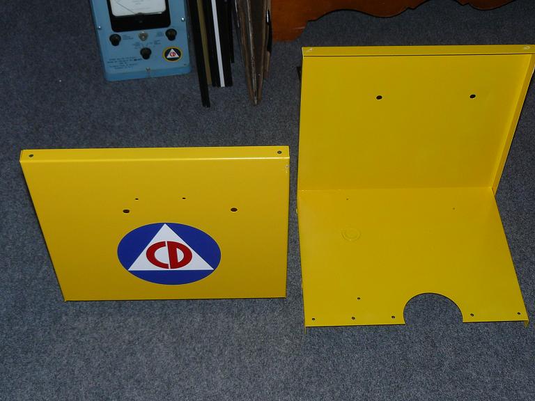
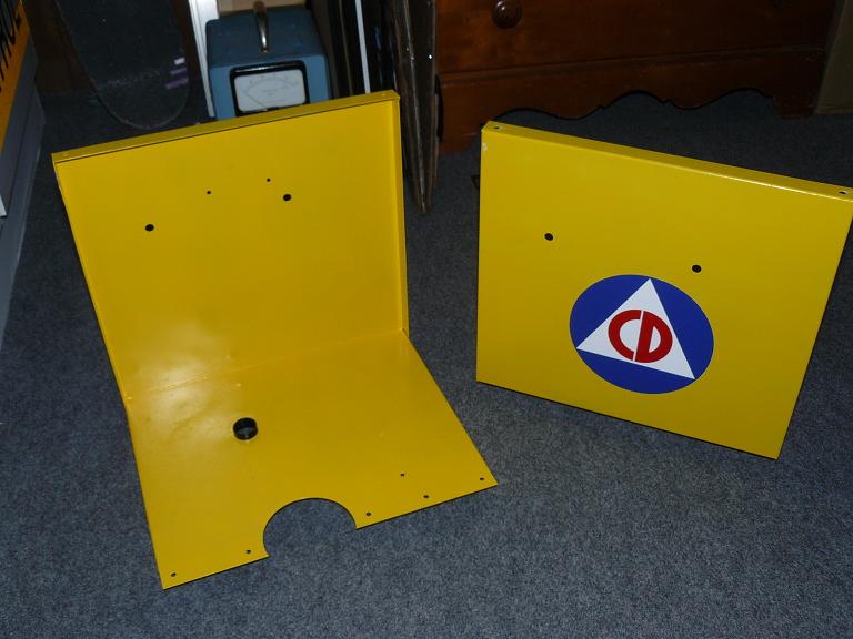
HERE ARE THOSE SAME PANELS WITH THEIR FINISH COAT AND NEW DECALS APPLIED
HERE ARE TWO PIC'S OF THE CHOPPER REASSEMBLED.
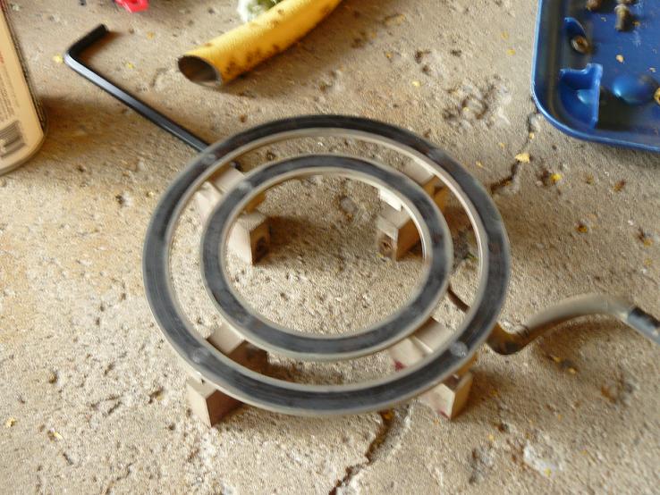
I ALSO MADE A NEW RUBBER GASKET FOR THE PROJECTOR.
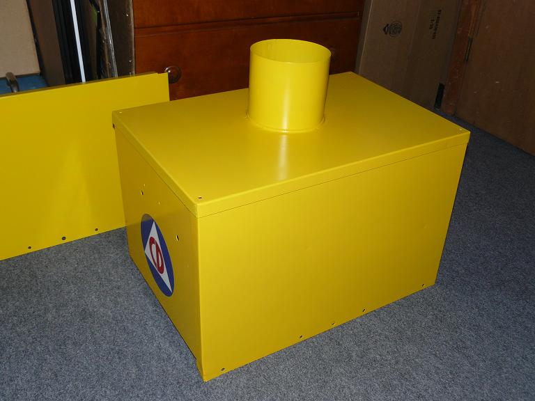
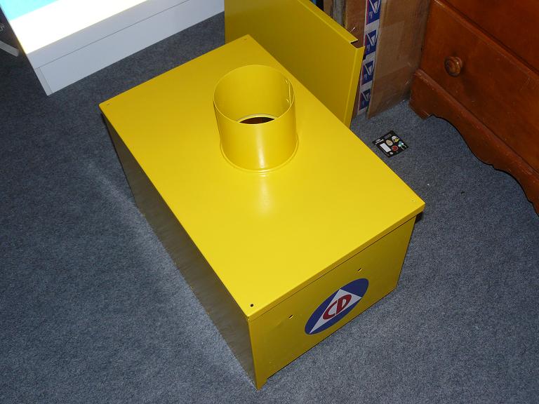
HERE IS THE DRY FIT OF THE ROTATOR CABINET
HERE'S THE RADIO REJOINING THE AR TIMER.
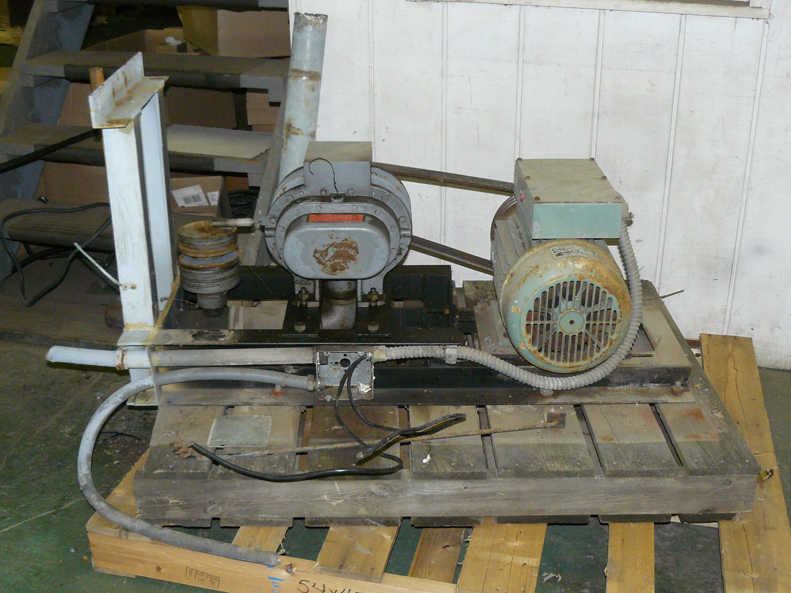
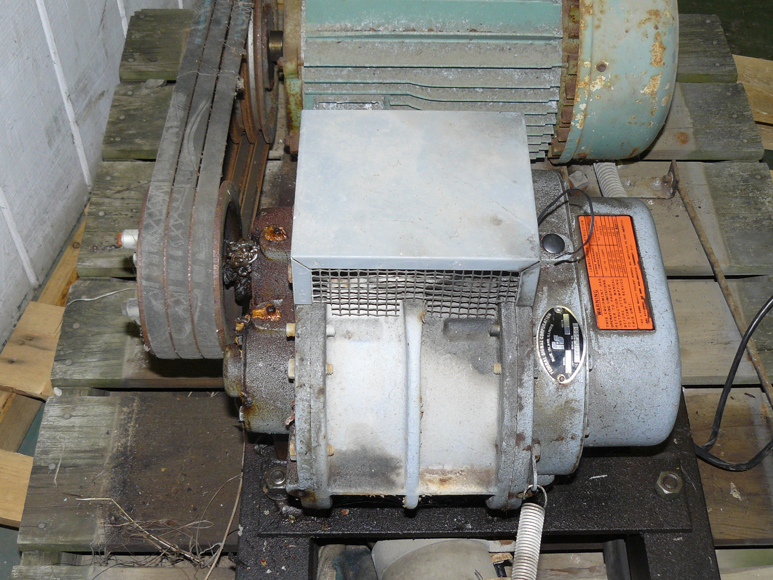
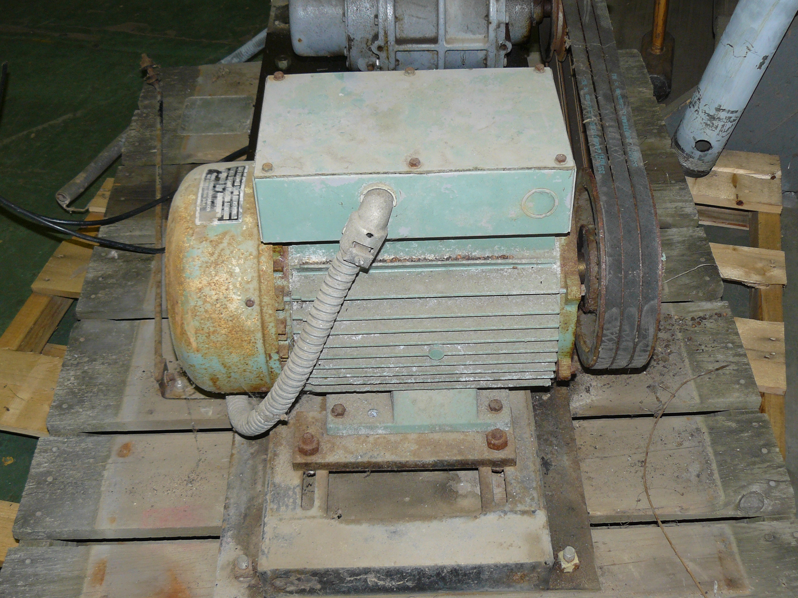
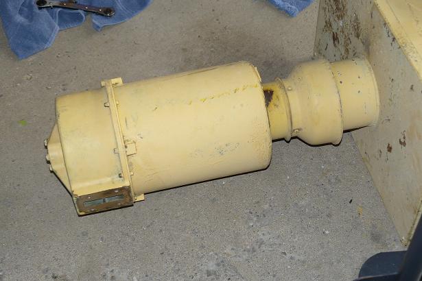
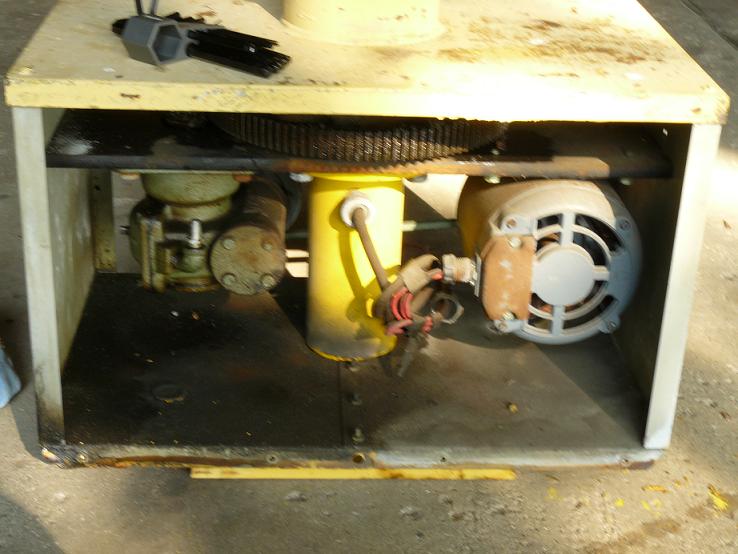
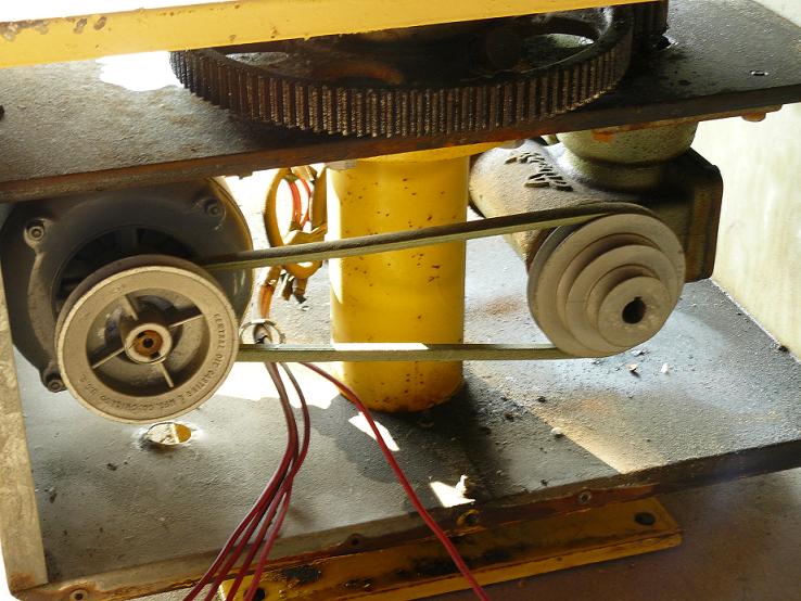
HERE'S THE SINGLE PHASE COMPRESSOR I GOT TO REPLACE THE THREE PHASE "BIRD NEST" COMPRESSOR.
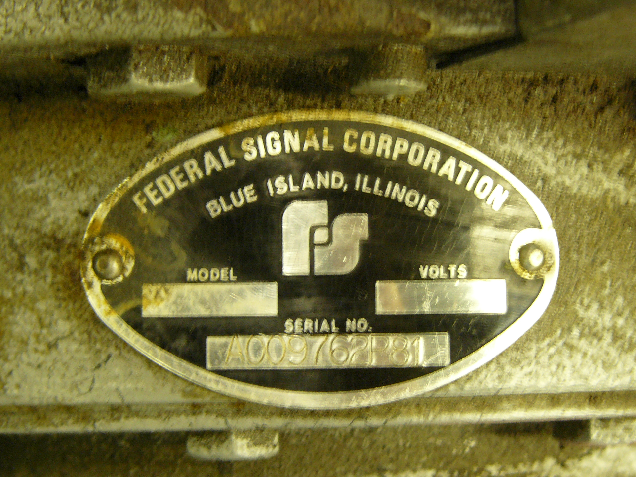
COMPRESSOR ID TAG
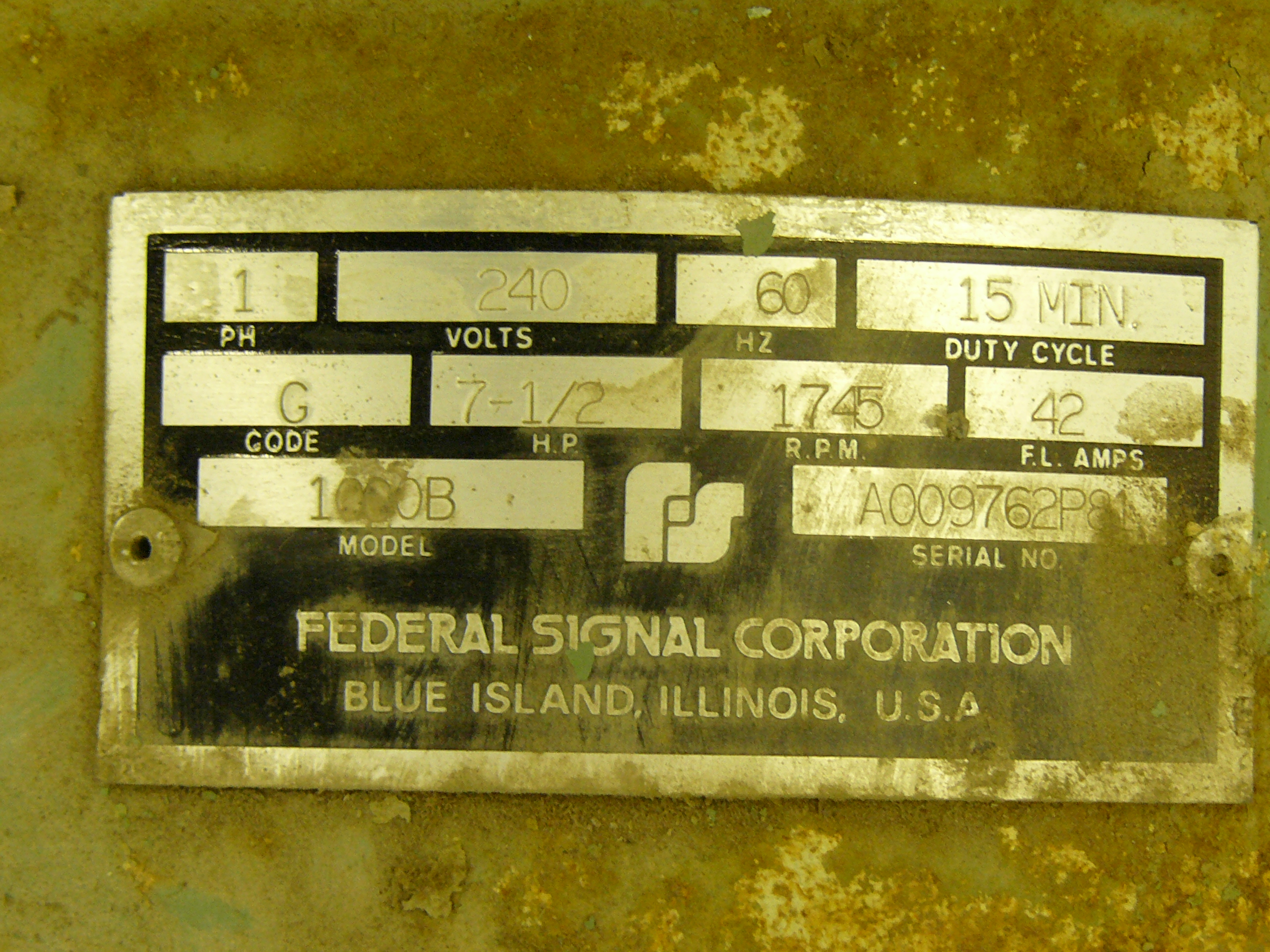
COMPRESSOR MOTOR TAG
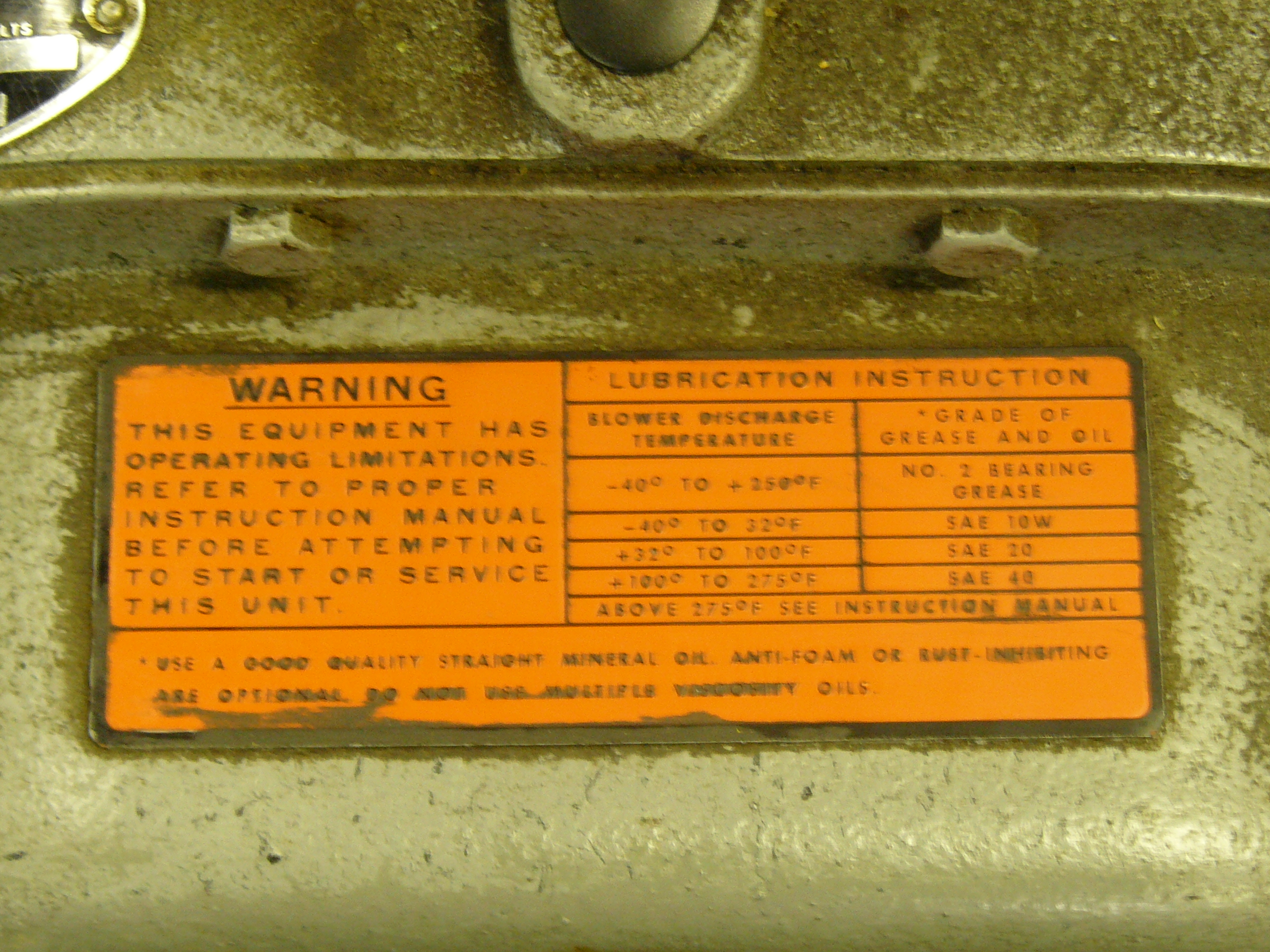
"LUBRICATION CHART" TAG ON THE COMPRESSOR
COMPRESSOR
SINGLE PHASE MOTOR.
THE BOX ON THE TOP IS A OVERLOAD DEVICE. IT HAS A RED RESET BUTTON.
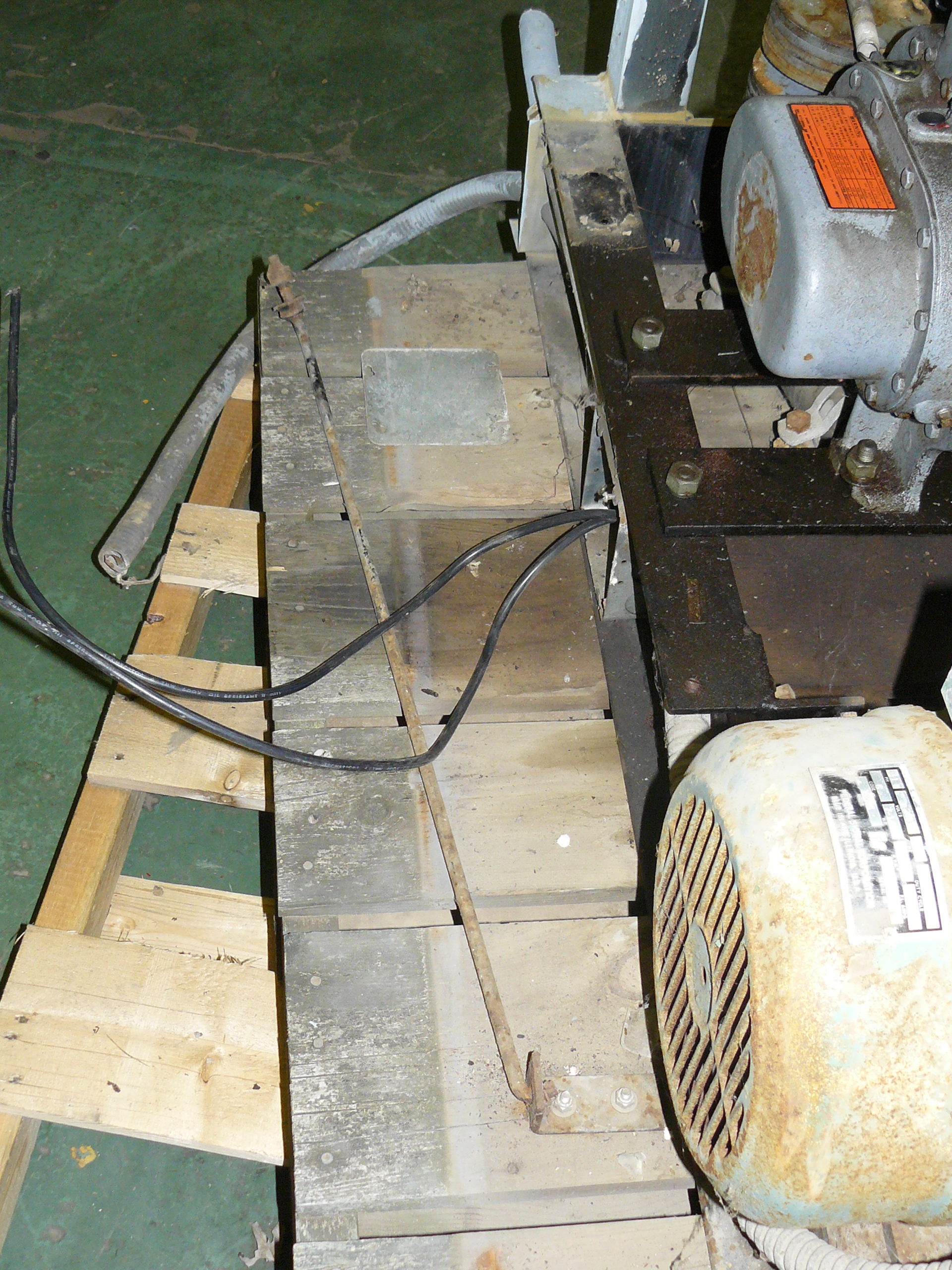
HERE'S A PIC OF THE SUPPORT ROD FOR THE COMPRESSOR COVER.
THIS IS THE NEWER STYLE, SO YOU CAN LIFT UP THE COVER AND TILT IT AWAY FROM YOU. THIS COMES IN HANDY WHILE WORKING ON
THE COMPRESSOR WHILE IT'S UP IN THE AIR, LIKE ON A WOODEN POLE.
Click here to go to the Thunderbolt restoration page continued section
|